
Types and structure of Valve Actuator
Types and structure of Valve Actuator
A Valve Actuator is a mechanical device that uses a power source to operate a valve. This power source can be electric, pneumatic (compressed air), or hydraulic (the flow of oil). There are two main types of actuators, one for each of the two main types of valves that require them.
Selection of the best actuator type for any application is dependent on many factors including:
- Valve type
- Power sources available
- Environment of installation
- Operational functions and characteristics
- Cost
Types of Valve Operation
There are two primary types of valve actuators. Understanding how a valve operates is the first step in choosing the appropriate actuator.
- Rotary Valve Actuators
As the name implies, rotary valve actuators produce the rotational motion needed to operate roatary valves such as ball, plug, and butterfly valves. Rotary actuators are available in many different styles, each with its own benefits. - Linear Valve Actuators
Linear valves such as a globe, gate, and pinch valves – due to their distinctly different operation – require actuators that are drastically different from the rotary type. These actuators must produce linear motion to operate the valve. They are also available in many styles.
Types of Valve Actuator
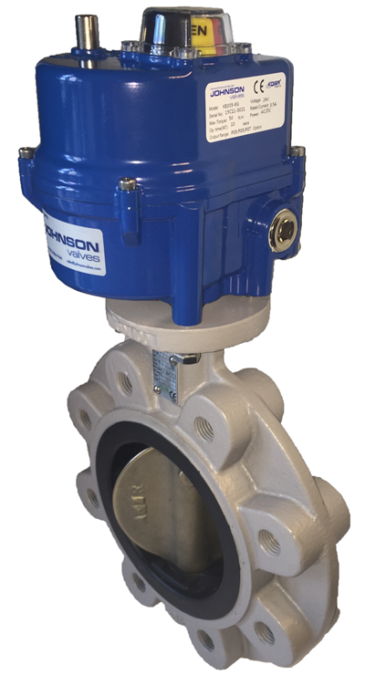 1-Electric Valves Actuators
This type of actuator is motor-driven or what the name implies is powered by electricity. They come in various designs and sizes to match different valve applications.
Depending on the design, the power will either be direct current (DC) or alternating current (AC). This electricity will supply the necessary torque to open or close the valve. Since electric actuators rely on electricity, it would fail to operate when there is a power outage.
This is a disadvantage especially at critical times when the valve is in the vital process of opening or closing and got interrupted. There are cases when valves are hard to turn because they are seldom used or handling sticky or abrasive materials. When this happens, the operators will have to specify electric actuators with extra torque so they can turn the valve with ease.
For added assurance that the valve will be controlled anytime it is needed to, it is recommended to attach manual control wheels or handles.
It can also prevent motors from burn out or overheat because of much energy exerted from turning sticking valves. In order to protect the motor, there are various ways that can be employed such as electric current limiting sensors, motor overheats or over-torque. No matter what the type and the design of actuators; overload protection should be attached on it to prevent malfunction due to a stuck valve.
2-Hydraulic Valves Actuators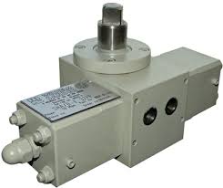
In contrast to electric actuators that rely on electricity to work, hydraulic actuators move mechanisms through water pressure or other fluid. They are commonly used in butterfly valves since it does not require a large opening within the pipe to control the flow of fluid. This type of actuator is not recommended to use in places which temperature reaches below freezing as when the water solidified, it will stop providing hydraulic energy needed for the operation.
3-Pneumatic Valves Actuators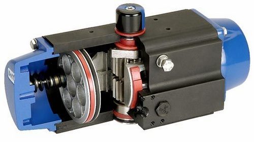
This device, on the other hand, takes energy from a change of air pressure to produce motion. There are various types of pneumatic valves actuators such as rotary actuators, single or double acting pneumatic cylinders and diaphragm actuators. They produce various motions that are capable of moving the valve in the required direction.
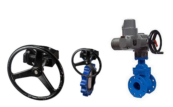
- Manual actuators are the most common type of valve actuators. Manual actuators include handwheels attached to the valve stem directly and handwheels attached through gears to provide a mechanical advantage.
- Electric motor actuators consist of reversible electric motors connected to the valve stem through a gear train that reduces rotational speed and increases torque.
- Pneumatic actuators use air pressure on either one or both sides of a diaphragm to provide the force to position the valve.
- Hydraulic actuators use a pressurized liquid on one or both sides of a piston to provide the force required to position the valve.
- Solenoid actuators have a magnetic slug attached to the valve stem. The force to position the valve comes from the magnetic attraction between the slug on the valve stem and the coil of the electromagnet in the valve actuator.


Leave a Reply
Want to join the discussion?Feel free to contribute!